
Learning AutoCAD for civil engineers is essential for creating accurate drawings, plans, sections, elevations and construction details used across all civil engineering projects. Civil engineers rely on AutoCAD to deliver precise architectural layouts, structural drawings, road alignment maps, drainage plans and reinforcement detailing. This guide explains AutoCAD basics, interface functions, essential commands, drafting workflows, layer management and plotting concepts—designed specifically for civil engineering beginners.
1. Understanding the AutoCAD Interface
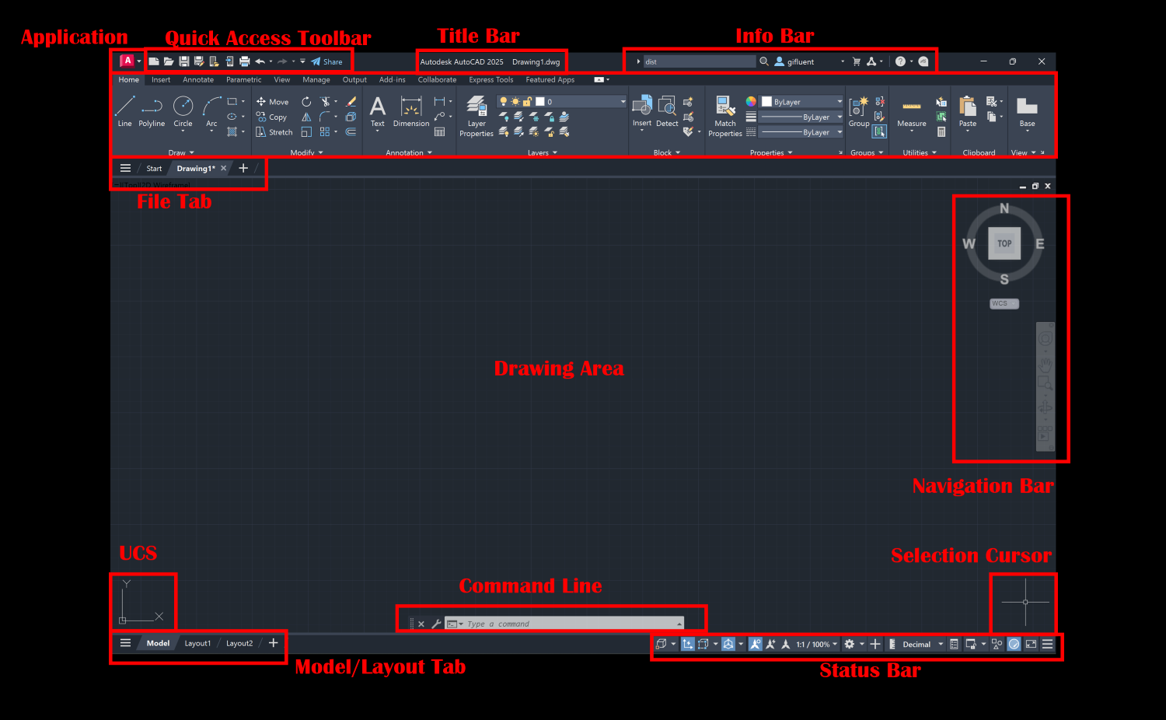
Below is a generic CAD-style workspace showing the ribbon, toolbars, drawing area and command line—similar to the AutoCAD environment.

4
The interface consists of:
Ribbon
Contains frequently used drawing, editing and annotation tools.
Drawing Area
The main workspace where lines, shapes and drawings are created.
Command Line
The single most important part of AutoCAD.
Civil engineers execute 80% of actions by typing commands.
Status Bar
Toggles grid, ortho mode, snap, tracking, scale and many drafting aids.
Understanding this layout makes drafting faster and easier.
2. Essential AutoCAD Commands Every Civil Engineer Must Learn
Mastering autocad commands for civil engineers improves drafting speed and accuracy in project drawings.
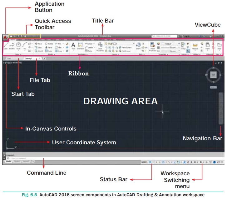
Here is a visual representation of the command bar + tools section typically found in CAD drafting interfaces:

Below are the core commands you will use daily on real projects:
| Command | Description |
|---|---|
| L | Draw straight lines |
| PL | Draw polylines |
| C | Draw circles |
| A | Draw arcs |
| REC | Draw rectangles |
| O | Offset for parallel copies |
| TR | Trim unwanted objects |
| EX | Extend objects to boundaries |
| CO | Copy |
| M | Move |
| MI | Mirror |
| F | Fillet edges |
| CHAMFER | Create angle corners |
| DIM | Add dimensions |
| H | Hatch in section drawings |
| LA | Layer management |
| Z | Zoom |
| P | Pan |
These 15–20 commands form the backbone of civil engineering drafting.
3. Coordinate Systems for Precise Drafting
AutoCAD uses coordinates to ensure accuracy in measurements.
Absolute Coordinates
(x, y) format → 0,0 is origin.
Relative Coordinates
@dx,dy → displacement from the last point.
Polar Coordinates
@distance<angle → used for angled lines.
Mastering coordinate entry makes structural and architectural drawings extremely accurate.
4. Layers in AutoCAD (Critical for Civil Drawings)
Proper layer management in civil engineering drawing autocad ensures clarity and professional standards.
Below is a CAD-style layer manager that resembles the layout used in AutoCAD:
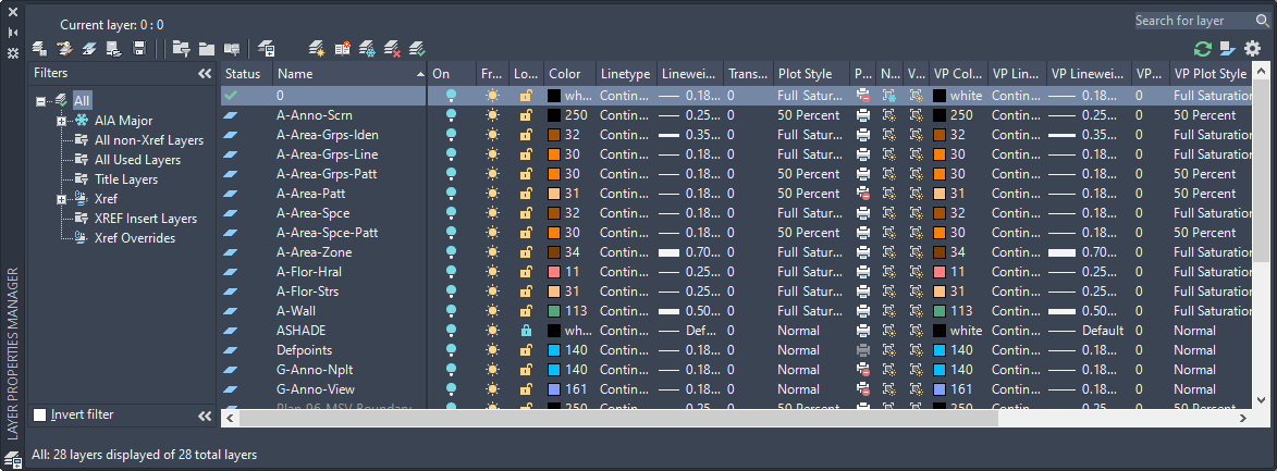
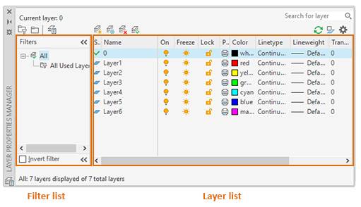

Civil engineers must NEVER draw on a single layer.
Layers help organize the drawing based on discipline.
Recommended Layer Setup
| Layer Name | Color | Use |
|---|---|---|
| Grid | Cyan | Column centerlines |
| Walls | Yellow | Architectural walls |
| Beams | Blue | RCC beams |
| Columns | Red | Column center & outlines |
| Slab | Green | Structural slabs |
| Dimensions | Magenta | All dimensioning |
| Text | White | Notes, levels, annotations |
| Hatch | Gray | Section hatches |
Pro tip:
Always assign proper lineweight and color so that printed drawings appear professional.
5. How Civil Engineers Use AutoCAD in Real Projects
Civil engineers rely on AutoCAD for:
- Floor plans
- Column layouts
- Footing drawings
- Beam centerlines
- Slab shuttering
- Reinforcement detailing
- Road cross-sections
- Drainage and water pipelines
- Septic tank details
- Retaining wall drawings
- Site layout & landscaping plans
- Contour and topographic drawings
Here are generic CAD examples showing plans, sections and technical drawings:


6
6. Dimensioning & Annotation Standards
Dimensions must be:
- Clear
- Uniform
- Aligned
- Easy to read
- Scaled correctly
Civil engineers should use:
- Linear dimensions
- Aligned dimensions
- Radius and diameter annotations
- Leader notes for details
- Levels and elevations
Example of dimensioning style:


Dimension text height should be 2.5–3 mm for printed A3/A2 drawings.
7. Creating Plans, Sections and Elevations in AutoCAD
Floor Plans Include:
- Wall outlines
- Doors and windows
- Stairs
- Room names
- Dimensions
- Levels
Sections Include:
- Floor heights
- Structural levels
- Reinforcement zones
- Foundation depth
Elevations Include:
- Openings
- Architectural elements
- Building façade detail
These drawings must follow standard conventions so that contractors and site engineers can understand them easily.
8. Plotting and Printing (PDF or Hard Copy)
Good drawings require correct plotting:
- Use CTRL + P
- Choose the right CTB file (lineweight style)
- Set paper size (A1, A2, A3, etc.)
- Use standard scale (1:50, 1:100)
- Check preview before printing
Incorrect plotting leads to unreadable drawings on site.
9. Speed Up Drafting with AutoCAD Shortcuts
| Action | Shortcut |
|---|---|
| Repeat command | Spacebar |
| Undo | CTRL + Z |
| Redo | CTRL + Y |
| Zoom Extents | Z + Enter + E |
| Ortho Mode | F8 |
| Object Snap | F3 |
| Pan | Press Mouse Wheel |
Mastering shortcuts can increase your drafting speed by 50%.
10. Common Mistakes Beginners Must Avoid
- Drawing everything on one layer
- No OSNAP → inaccurate drawings
- Using wrong units
- Excessive trimming instead of strategic drafting
- Overlapping lines
- Not cleaning drawings (use PURGE)
- Wrong scale during plotting
- Using images instead of linework
Civil engineers must maintain accuracy and clarity at all times.
Conclusion
AutoCAD is one of the most essential tools for civil engineers, enabling precise and professional-quality drawings for design, planning and construction. Mastering commands, layers, dimensions, templates and plotting ensures that your drawings meet industry standards. With consistent practice and understanding of workflows, AutoCAD becomes a powerful asset throughout your engineering career.
Recommended Resources
Autodesk CAD Learning Center
https://www.autodesk.com/solutions/cad-software
NPTEL Engineering Drawing & CAD
https://nptel.ac.in
CADTutor Tutorials
https://www.cadtutor.net